- A visual reference guide to disassemble, examine, and reassemble your Garmin Montana GPSr.
- Requires a steady hand and plenty of patience.
- Necessary tools include a T6 torx driver and a small jewelers flat blade screwdriver.
Disassembly
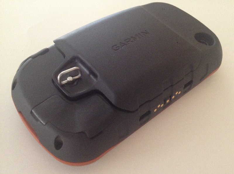
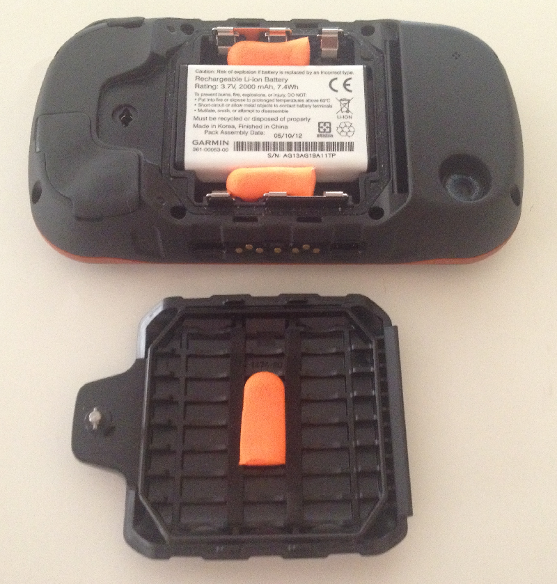
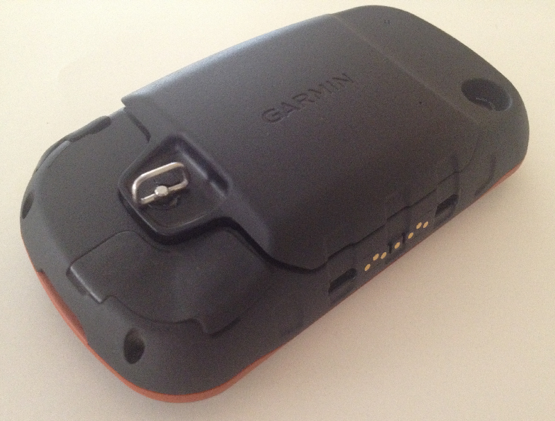
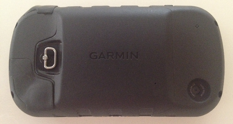
1. Release and remove the battery cover.
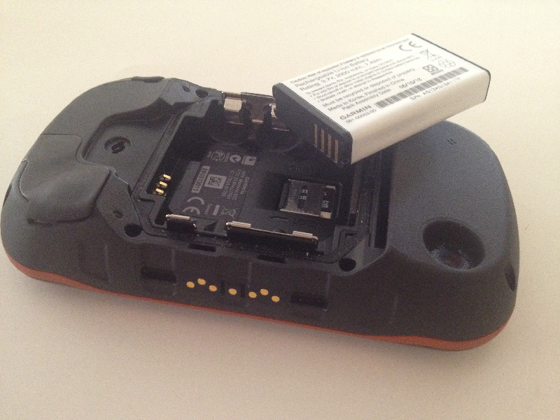
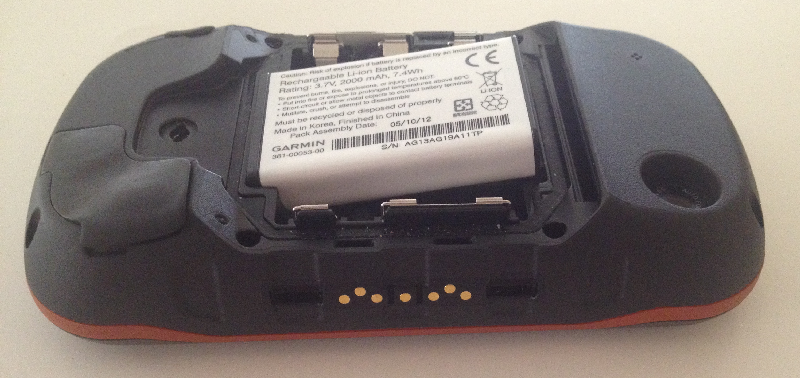
2. Remove battery.
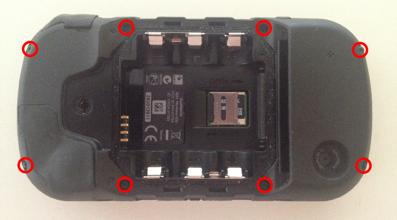
3. Remove eight (8) T6 Torx screws.

4. Carefully separate the two halves, taking care not to damage the LCD ribbon and power wires.
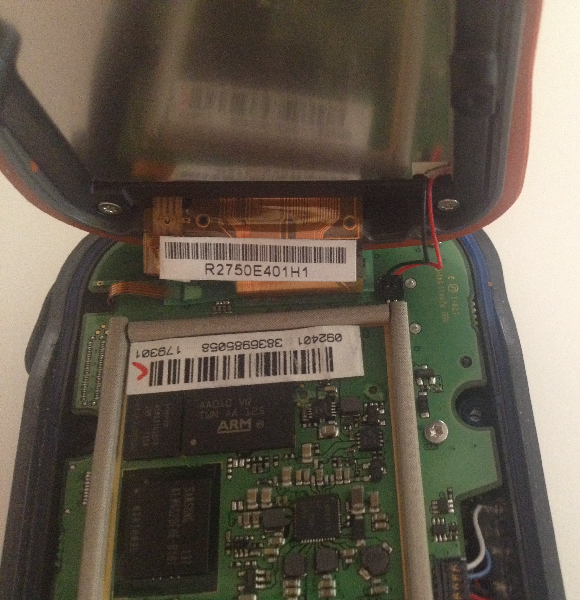
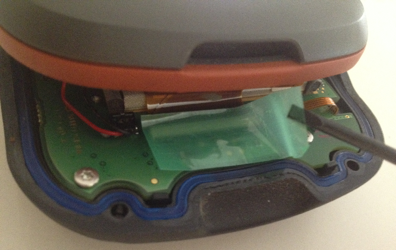
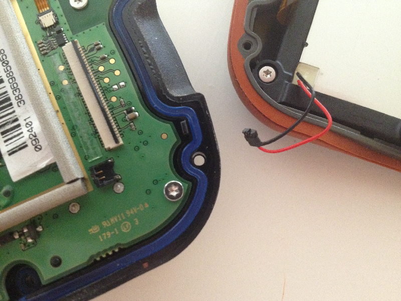
5. Position the two halves for access to the LCD ribbon and power connectors.
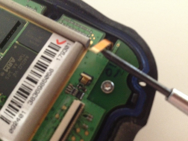
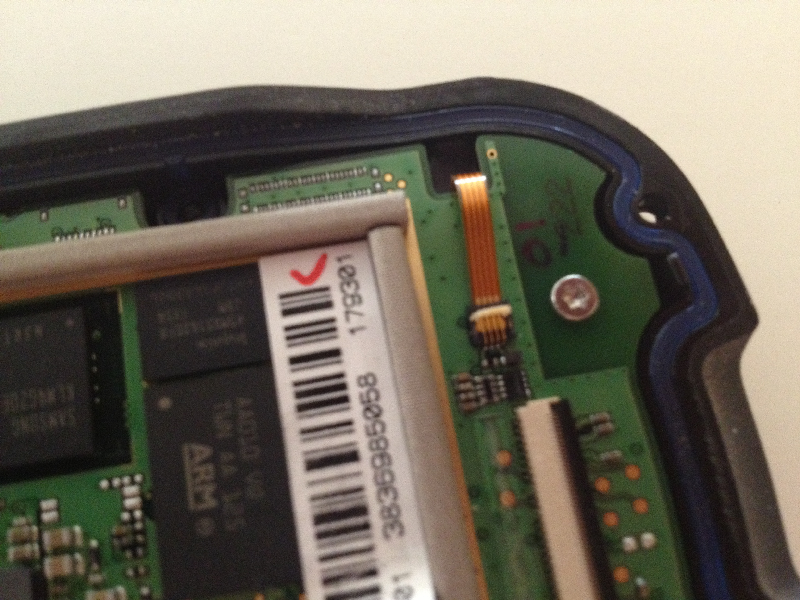
6. Carefully peel back and remove the protective tape.
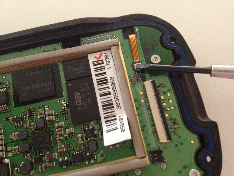
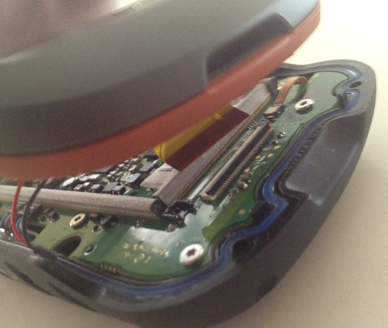
7. Insert flat blade screwdriver under ribbon connector lock and rotate screwdriver to unlocked connector.
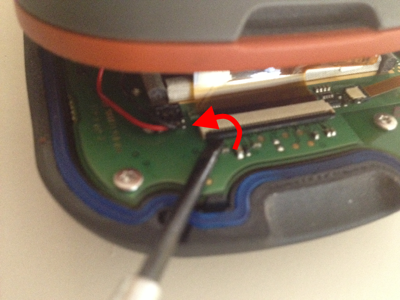
8. Gently slide LCD ribbon out of ribbon connector.
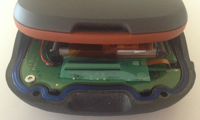
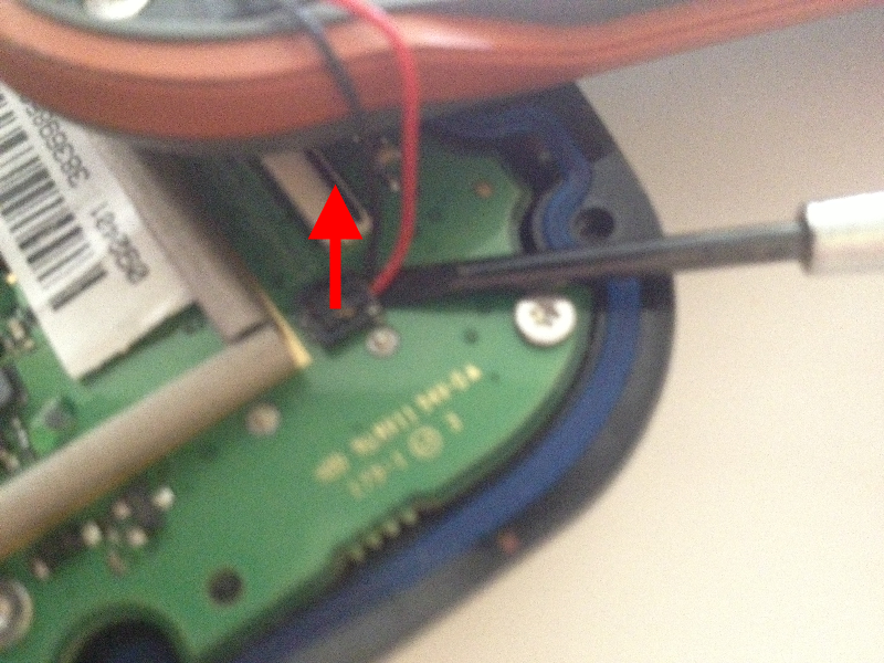
9. Use flat blade screwdriver to pop LCD power harness straight up out of connector.
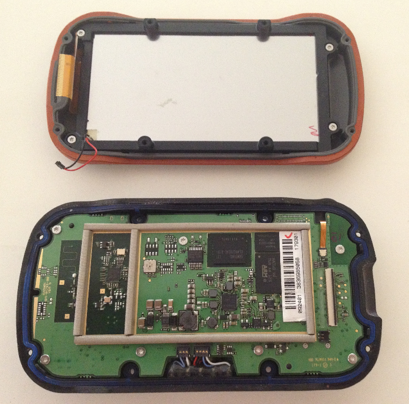
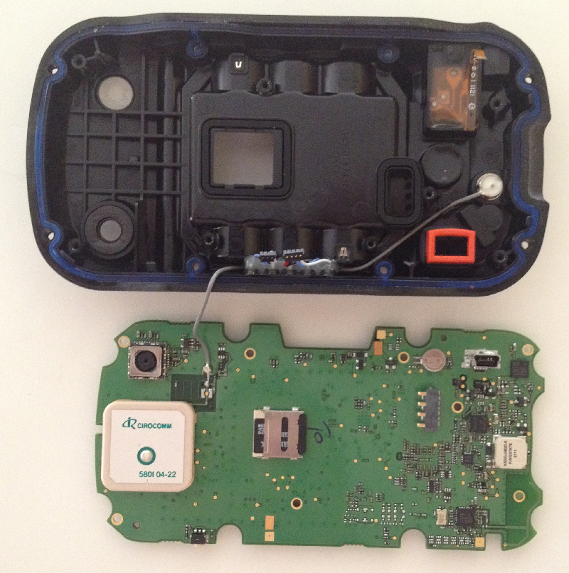
10. Finish separating the two halves.
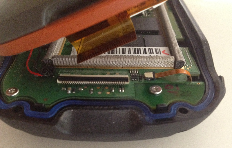
11. The LCD and mainboard are completely separated.
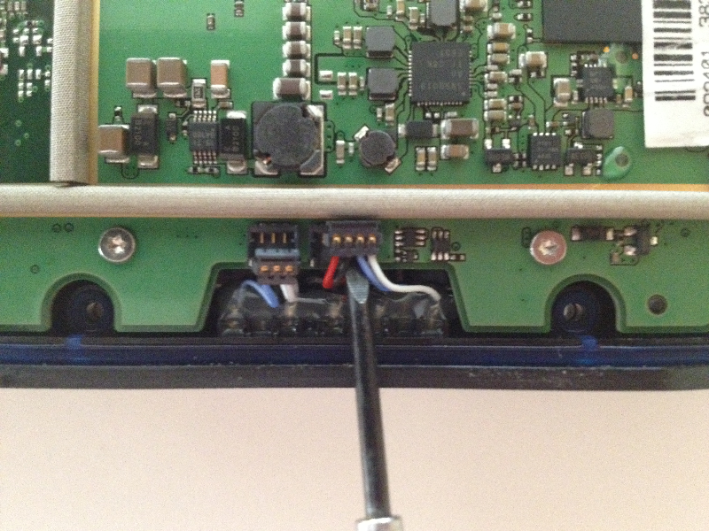
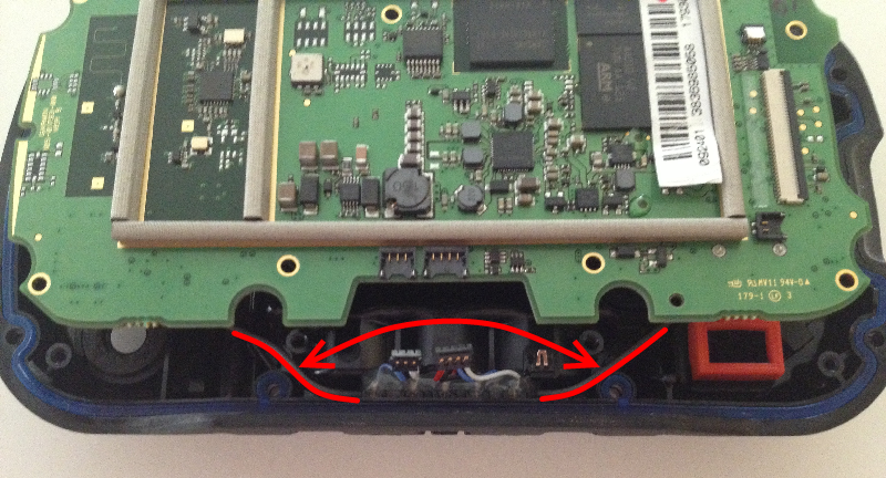
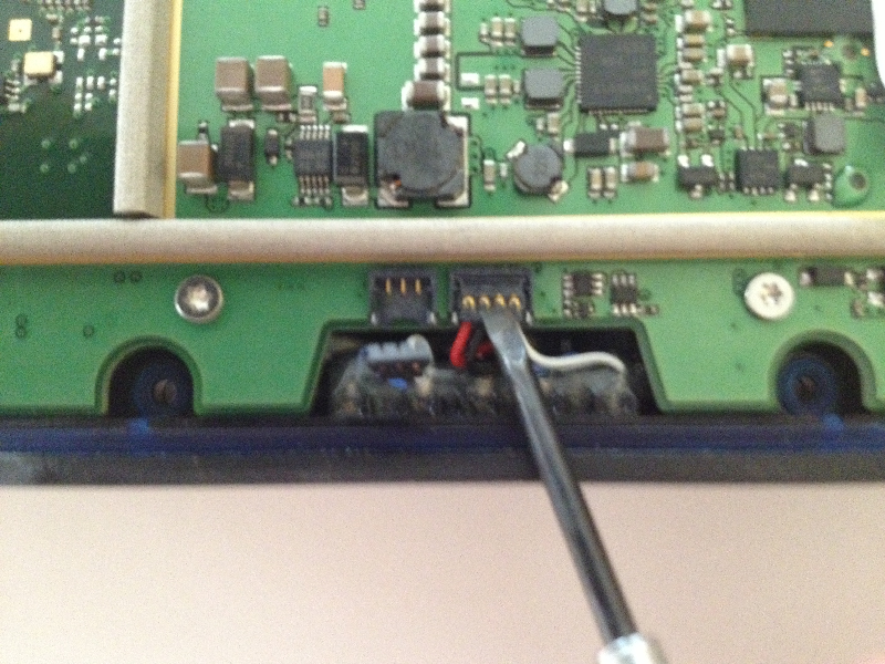
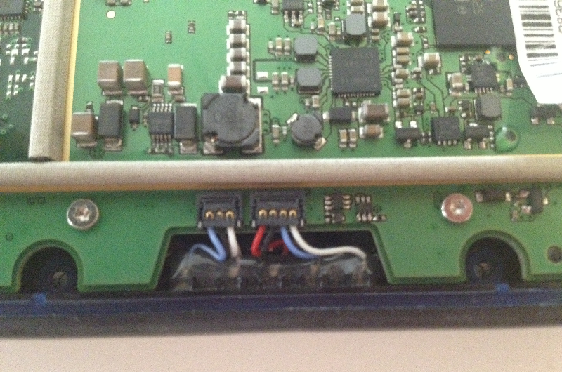
12. Use small flat blade screwdriver to pop docking port harness up and out of connector.
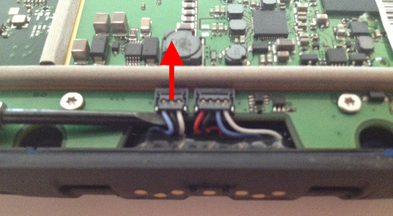
13. Harness is properly released from mainboard.
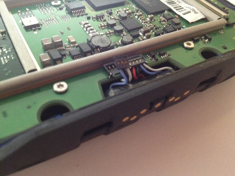
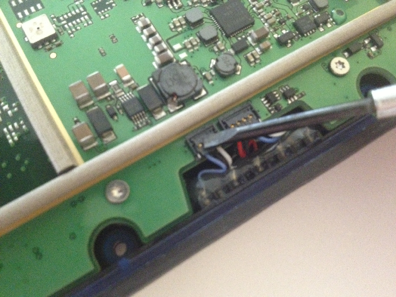
14. Repeat process for additional docking port connector.
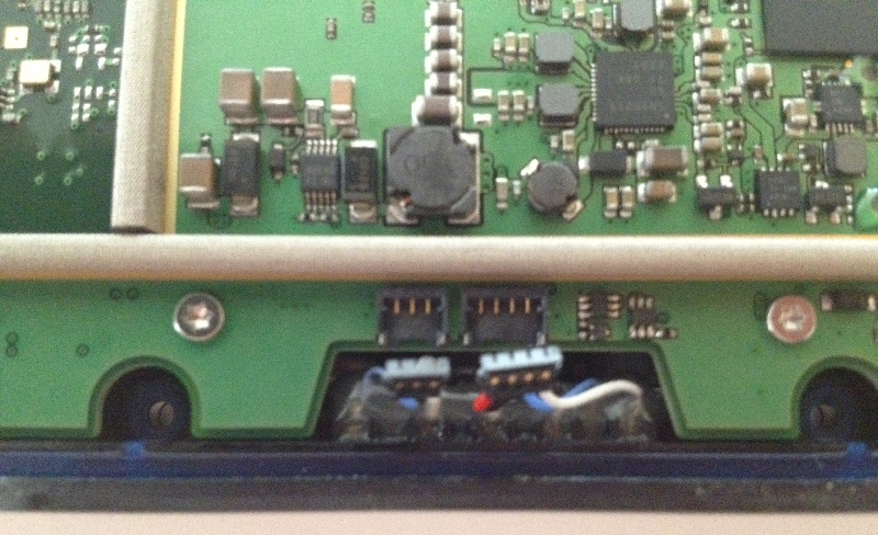
15. Both docking port connectors properly released.
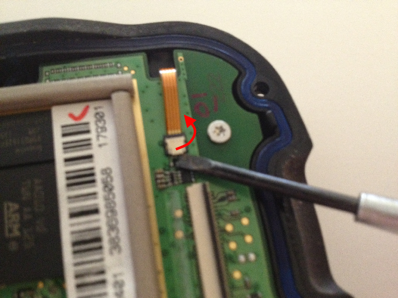
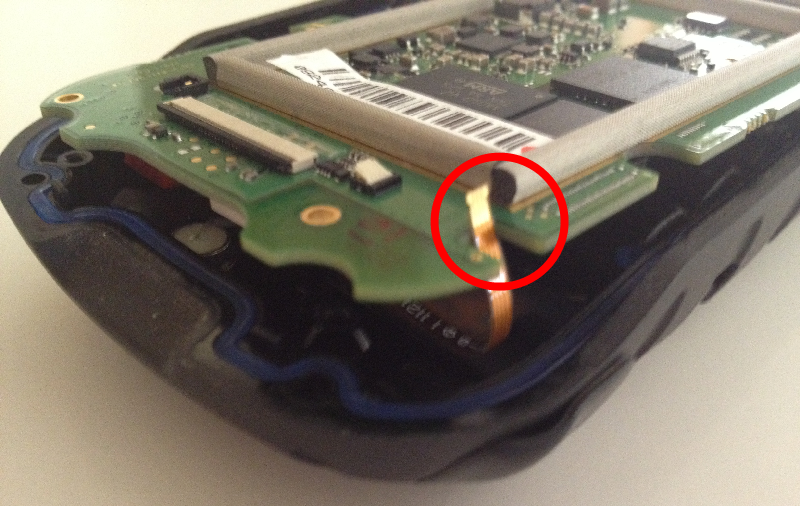
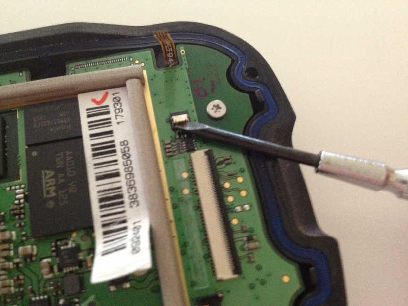
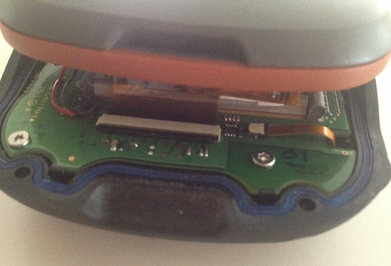
16. Unlock audio jack ribbon connector.
17. Gently slide audio jack ribbon from connector.
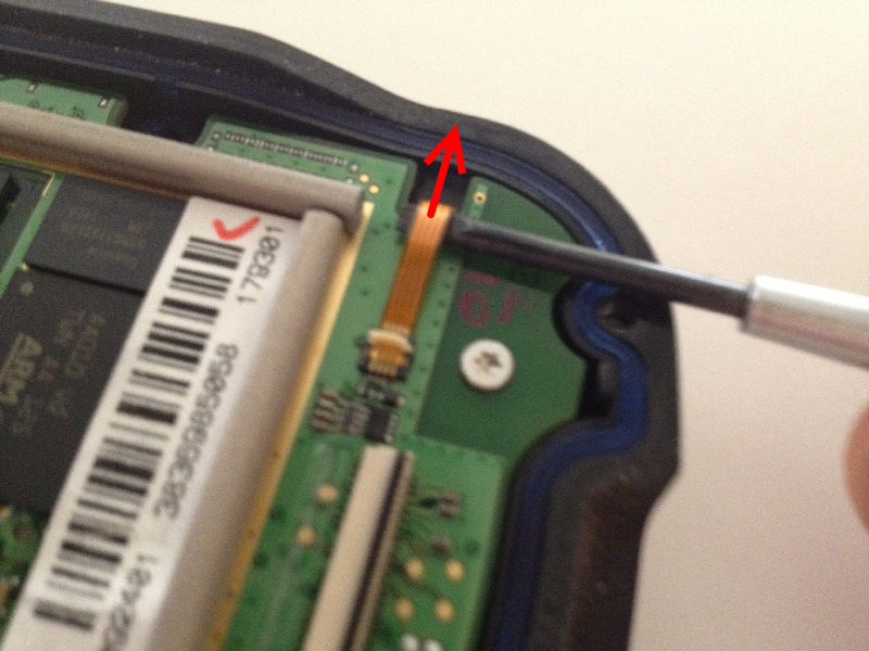
18. Audio jack ribbon safely disconnected from mainboard.
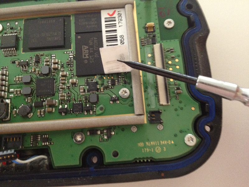
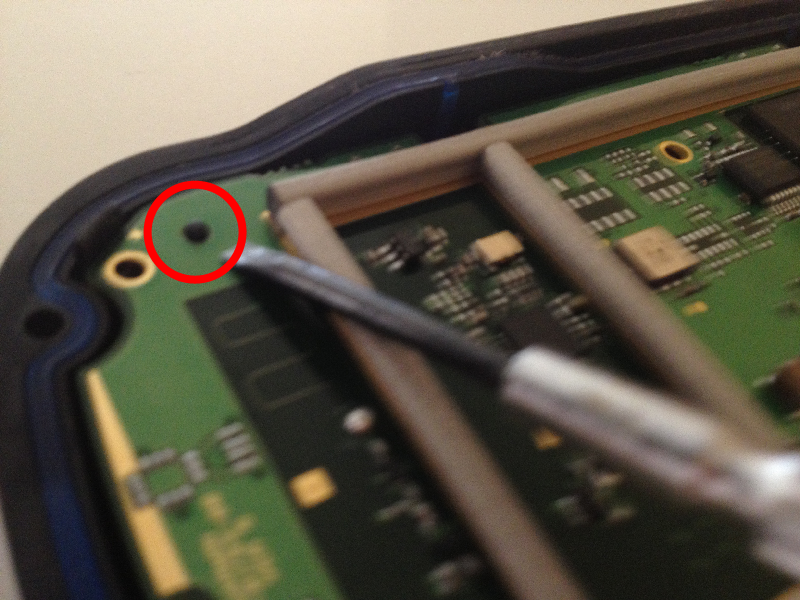
19. Carefully peel back label to reveal hidden screw.
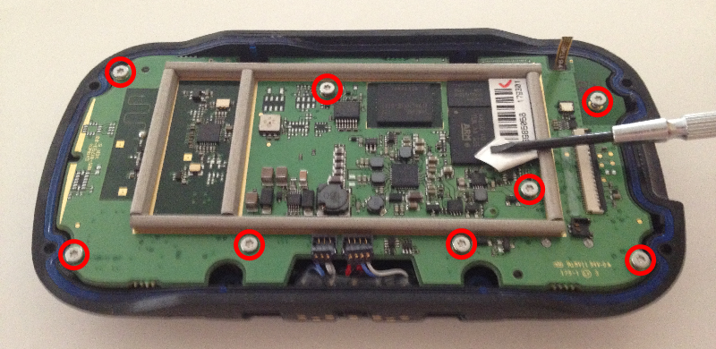
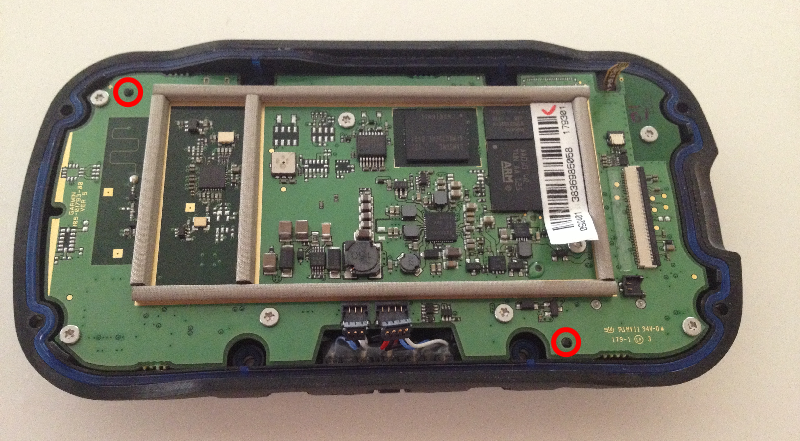
20. Remove eight (8) T6 Torx screws.
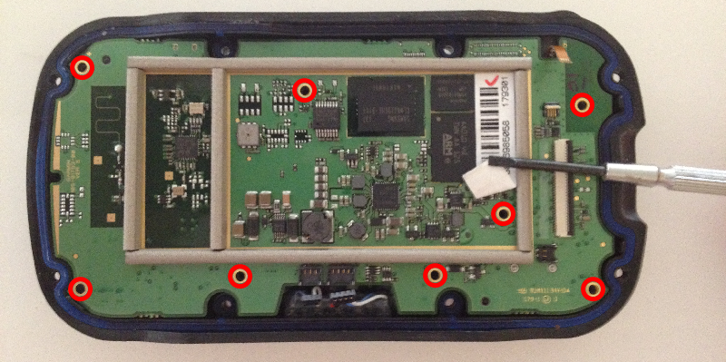
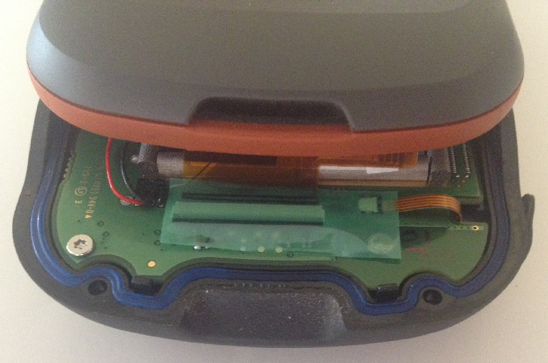
21. Carefully lift mainboard out of chassis.
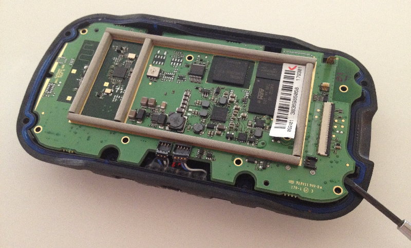
22. Disassembly is complete.
Reassembly
1. Carefully place mainboard into chassis taking care not to pinch aux antenna jack wire.
2. Locate audio jack ribbon into proper position.
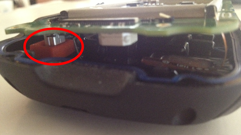
3. Carefully guide USB jack into gasket sleeve.
4. Make certain mainboard is properly aligned on guide pins.
5. Start eight (8) T6 Torx screws, but do not tighten.
6. Verify correct guide pin alignment and then tighten (do not over tighten) T6 Torx screws from center outward.
7. Open audio jack ribbon connector lock.
8. Guide audio jack ribbon into connector.
9. Lock audio jack ribbon connector.
10. Snap docking port harness into mainboard connector.
11. Repeat for additional docking port harness and connector.
12. Docking port harness and connectors properly secured.
13. Bring two halves together, aligning LCD ribbon with connector on mainboard.
14. Carefully install LCD ribbon and lock ribbon connector on mainboard. Snap LCD power harness into place.
15. Reapply protective tape.
16. Start eight (8) T6 Torx screws, then tighten (do not over tighten) from the center outward.
17. Install battery.
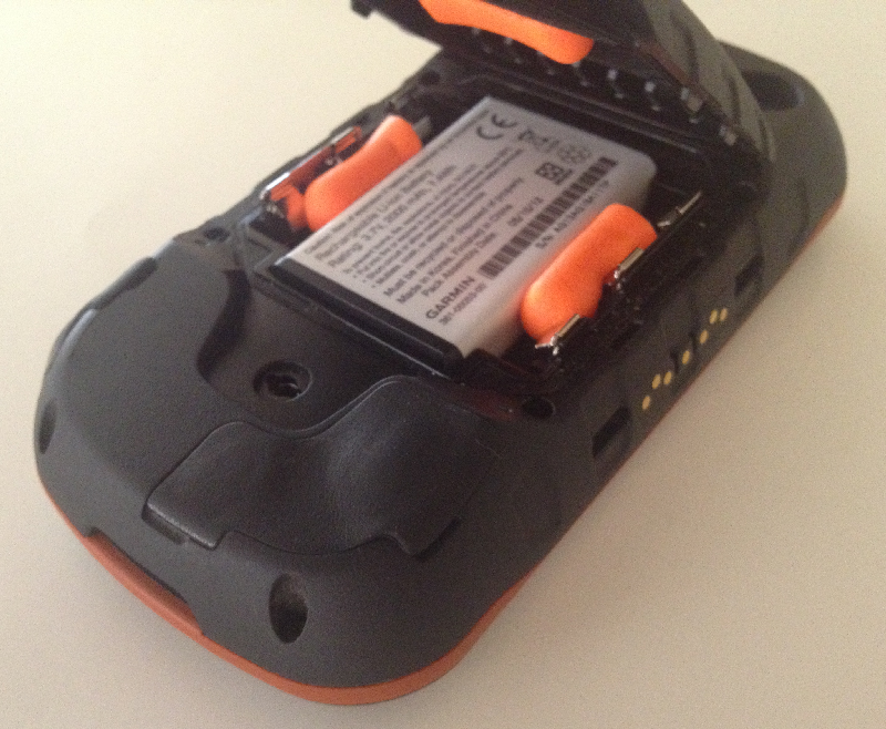
18. Place foam earplugs as desired.
19. Install battery cover into hinge.
20. Close battery cover.
21. Lock battery cover.
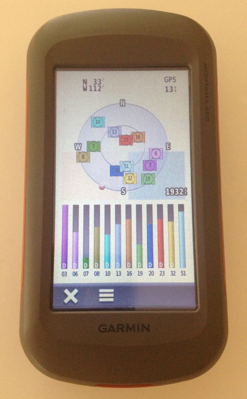
22. Power up and test Montana GPSr function.
23. Reassembly is complete.